|
On the
nature of electromagnetic induction as described by Lenz’s Law: the
magnetic field seems to be constructed from two counter-rotating,
helical spirals, which are centred along its North or South poles
respectively
In this
first diagram, we can see what any N-S magnetic field looks like, when
it is studied in close detail using ferrofluids (see
arxiv.org
or
www.ferrocell.us ):
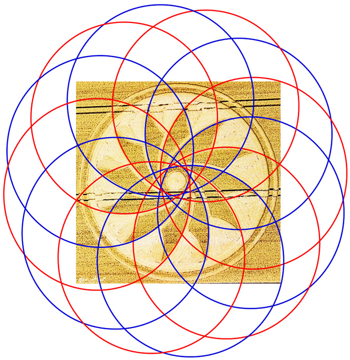
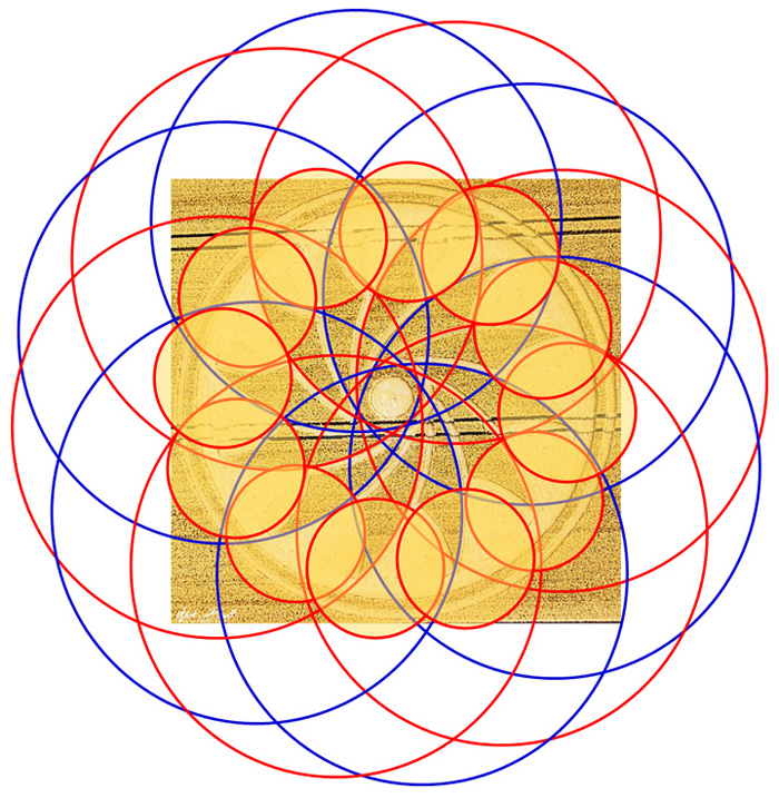
A new crop
picture at Clifford’s Hill only shows the central or near-axial part of
this N-S field, although the complete field (as represented above by red
or blue circles) has been drawn in many different crop pictures from the
past (see for example
cropcircles.lucypringle.co.uk
or
cropcircles.lucypringle.co.uk
or
cropcircles.lucypringle.co.uk ).
In this
second diagram, we can see how 12 “small circles” or small charged
particles (shaded in yellow) within a nearby conductor may be induced to
move in an anti-clockwise, circular or “pinwheel” path, as a consequence
of their coming into contact with just one (clockwise North or
anti-clockwise South) of those two counter-rotating, helical spirals:
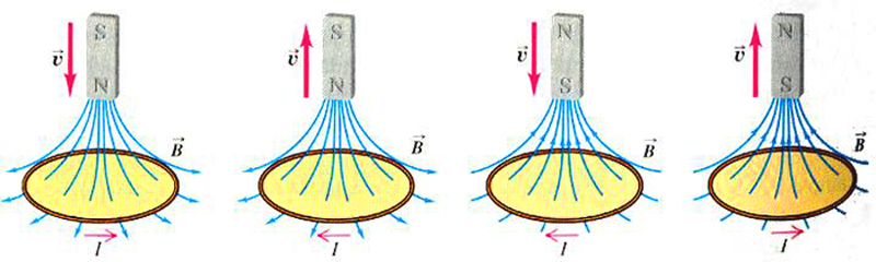
A typical
diagram from physics textbooks is shown below. It describes what happens
when a N-S magnet moves parallel to its long axis, relative to a nearby
ring made of conductive material (such as copper). Yet it does not
explain why this happens mechanistically:
They teach
physics in the schools today like they taught genetics in 1950, before
the discovery of double-helical DNA
This sketch
from a physics textbook does not show any “rotating sub-structure” for a
N-S magnetic field, and so the ability of a moving magnet to induce a
“rotating current” of electrons in a nearby conductor seems like
“magic”!
What they
teach in physics today is somewhat analogous to how they used to teach
genetics in the schools, before the discovery of double-helical DNA. How
could the specific information from a “gene” in one generation be passed
on accurately to the next generation? Nobody then knew! Now we know that
one strand of the DNA goes to one daughter cell, while the other strand
of DNA goes to the other daughter cell, and each strand carries all of
the information as needed.
Likewise in
the case of modern physics, they ask the students to memorize certain
abstract equations which agree with what is observed, but they do not
teach that the N-S magnetic field has any kind of “rotating
sub-structure” (like that which has been drawn many times in crops, or
as has been visualized using ferrofluids). Why should the electrons of a
conductor rotate in a circular path, as some N-S magnet comes close?
“Nobody knows”, they tell their students. It is just another equation
which has to be memorized.
Such
current-inductive effects are usually described in terms of “Lenz’s
Law”, which may be derived from a sideways “Lorentz force” or
“right-hand rule”, as seen for any magnet moving relative to a linear
conductor. No mechanistic explanations or drawings are ever supplied.
In summary,
two counter-rotating “helical spirals” from any N-S magnetic field seem
to be what induces a sideways or circular “pinwheel” motion of electrons
or other charged particles, for a physical magnet in relative motion to
a nearby conductor.
Some brief
speculations on advanced physics as shown to us by friendly
extra-terrestrials, and the possibility for making electromagnetic
generators with improved efficiencies here on Earth
Why is
relative motion required to produce such inductive effects? Two charged
particles can attract or repel one another quite easily while at rest,
relative to one another, as can the North or South poles of two
stationary magnets.
It may be
that the two “counter-rotating spirals” within any magnetic field remain
out-of-contact or “hidden” from our usual 4-D spacetime x-y-z-t,
until relative motion changes the angular path through time for a magnet
moving relative to a nearby conductor. This might bring some kind of
partial energy from those “hidden spirals” into our 4-D spacetime, so
that they can cause electrons in a nearby conductor to move in a
sideways in a “pinwheel” motion around the centre.
It also
seems possible that an underlying symmetry of “spin ˝” for the electron,
in some higher set of dimensions, may cause us to see two different
“helical spirals” for a moving magnet when they intersect with our 4-D
spacetime. By this model, each “hidden spiral” would counter-rotate
relative to the other around magnetic North or South poles respectively.
The symmetry of counter-rotation is more of a “3-D inversion” than a
“2-D mirror plane”, and thus would require two orthogonal planes of
“spin” in at least four spatial dimensions w-x-y-z.
Whatever the
true situation, one thing is clear: the extra-terrestrials who fly
around our galaxy in UFOs, or make energy almost magically using
technologies which we have not developed yet, do not follow the same
“laws of physics” which are taught by indoctrination to millions of
otherwise eager students in the schools. So we should try, as much as
possible, to study all of the available facts, and raise ourselves up to
their level as best we can.
Can we build
electromagnetic generators with improved efficiencies and less “back EMF”?
Such
concerns are of great relevance to the question of whether we can build
electromagnetic generators with improved efficiencies here on Earth? The
major loss of efficiency for any generator comes about when electrical
current induced in a nearby conductor (or wire coil) forms a new and
transient magnetic field, which opposes the motion of any physical
magnet that created it. This is called “back EMF”.
At least
three respected inventors (namely Bruce dePalma, Adam Trombly and
Paramahamsa Tewari) have shown
that “back EMF” is not a “law of nature”, but rather a kind of
undesirable “electromagnetic friction” which can be reduced to some
extent (see
brucedepalma.com
or
www.youtube.com
or
www.youtube.com
or
www.tewari.org
or
www.youtube.com ).
All three of those inventors have made better generators of clever
design, which reduce the ratio of back-EMF to electrical current
produced, generally by making most of the conductive paths linear rather
than circular (so that they work by a Lorentz force rather than by
Lenz’s Law).
Many novel
designs for improved electromagnetic generators have been drawn in crops
over the years, and we understand what most of those designs mean, and
why they should work better than current designs for “standard” but
less-efficient generators here on Earth. Personally I have tried to
interest several large companies to produce and test small-scale models
of these “crop circle generators”, which should show reduced back-EMF,
in a fashion fully-consistent with known laws of physics as taught in
universities. Yet their upper-management executives cannot seem to get
beyond a widespread perception that “all crop circles are made using
rope and boards”. Thus no progress has been made so far, even if some of
the low-level engineers are in favour.
Crop-drawn
images of “solar energy” on July 14, 2018, and now “electromagnetic
energy” on July 21, 2018: perhaps the friendly E.T.’s are trying to tell
us something?
The crop
picture previous to this one appeared on July 14 next to a large “solar
energy farm” at Muncombe Hill in Somerset. Now on July 21, we can see
the image of “current induction by a magnetic field”, drawn at
Clifford’s Hill in Wiltshire:
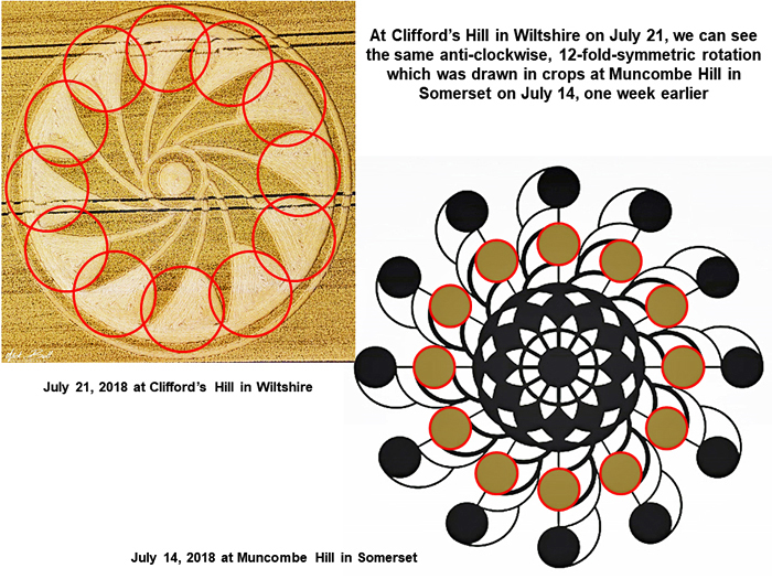
Both of
these “clean-energy” crop pictures show similar images of
anti-clockwise, 12-fold symmetric rotation. When sunlight shines down on
a conductive surface, or when a magnet approaches a conductive surface,
this may cause many small charged particles (or electrons) to move
circularly in the shape of a “pinwheel”, and thereby create useful
electricity for human use.
Making
improved solar-energy cells using graphene?
The last
crop picture prior to this one, at Muncombe Hill on July 14, 2018,
resembles the image of a new scientific discovery made in 2017. It was
discovered then that small “nanowires” could be used to control the flow
of electrons in graphene, which is a potential conductive material for
improved solar cells (see
taming-wild-electrons-graphene
or
wild-electrons-graphene ):
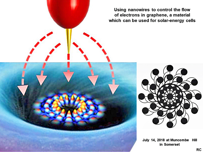
Because this
crop picture was drawn next to a large “solar energy farm”, its
technological suggestion becomes fairly easy to understand.
Improved
solar energy, improved electromagnetic energy: when will scientists and
engineers on Earth begin to open their minds, and study what is being
drawn mysteriously in the fields?
“Development
of the transistor took 5 years with Roswell, and would have taken 250
years without.”
--- Philip Corso (see
www.youtube.com )
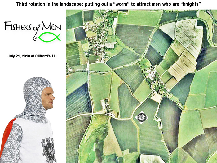
Why did the
crop artists draw an image of a “rotor spinning like a pinwheel” over a
“N-S magnetic field” at Clifford’s Hill on July 21, 2018? It was to tell
us how to turn from one viewing orientation in the local landscape
(East-up) to another (Northeast-up), so that we would be able to find
and perceive two different, overlapping meanings.
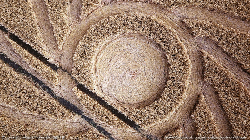
A crop
picture which appeared near Clifford’s Hill on July 21, 2018 seems to
represent a “spinning pinwheel”, or perhaps a “rotor spinning over a N-S
magnetic field”:
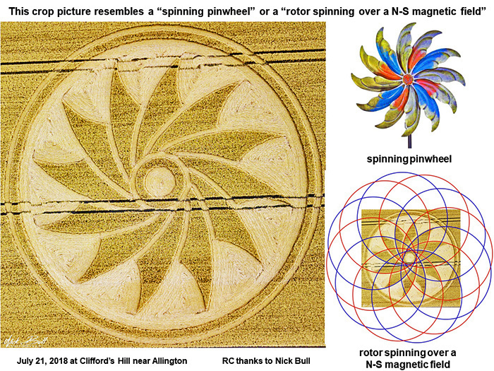
This is the
same kind of spinning motion which may be seen, for example, when a
conductive rotor made of copper spins over a single N-S magnet in a
homopolar motor.
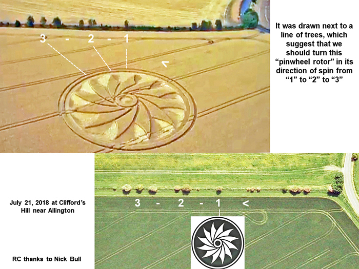
That crop
picture was drawn in the landscape next to a long line of trees which
seem to suggest, by their specific numbers, that we should turn this
“pinwheel rotor” in its indicated direction of spin by about 60o
anti-clockwise, or turn from tree-grouping “1” to tree-grouping “2” to
tree-grouping “3”:
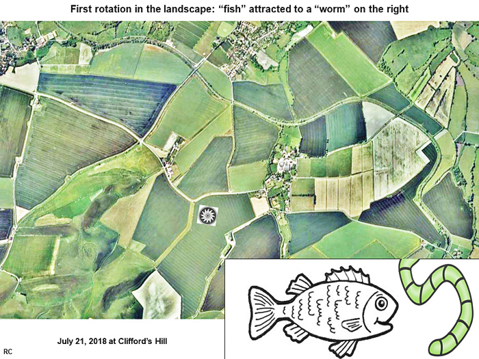
In its first
un-rotated orientation “1” which has the geographic direction of
“East-up”, we can see the humorous landscape image of a “bee” who seems
to be wearing a “jester’s hat”! That “bee” seems to be suggesting
comically to us with his “tongue” (while tasting a flower-like crop
picture) that we should turn this pinwheel from “1” to “2: to “3”, as
noted by the series of tree-groupings shown above:
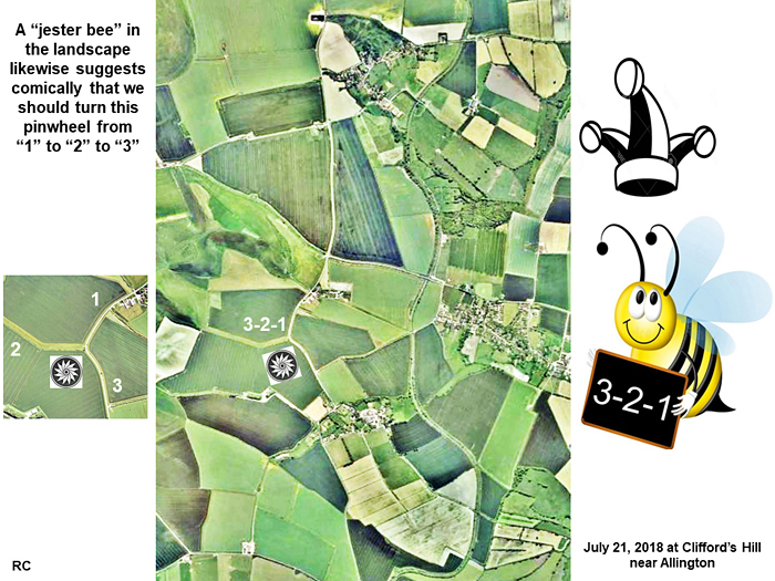
A triangular
junction of three different farm-paths (shown inset on the left) also
suggests some kind of anti-clockwise rotation from “1” to “2” to “3”.
The crop artist previously compared himself to a “bee” on June 24, 2018
near Yarnbury Castle (see
yarnbury castle 2018 ).
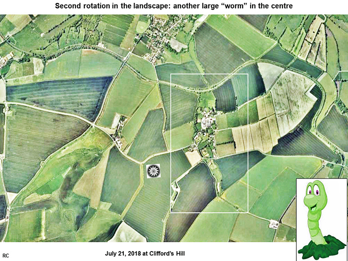
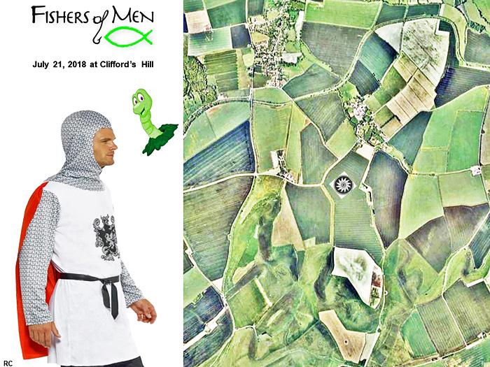
Meanwhile in
its second rotated orientation “3” which has the geographic direction of
“Northeast-up” (about 45o away in an anti-clockwise sense),
we can see something entirely different in the landscape which surrounds
this crop picture. Now we can see (on the left) what seems to be the
image of a “French soldier” (such as at the time of Napoleon), who is
wearing a military “cockade” on his chest (the ribbon-like crop picture
as drawn):
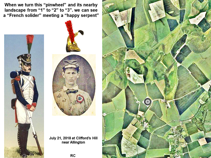
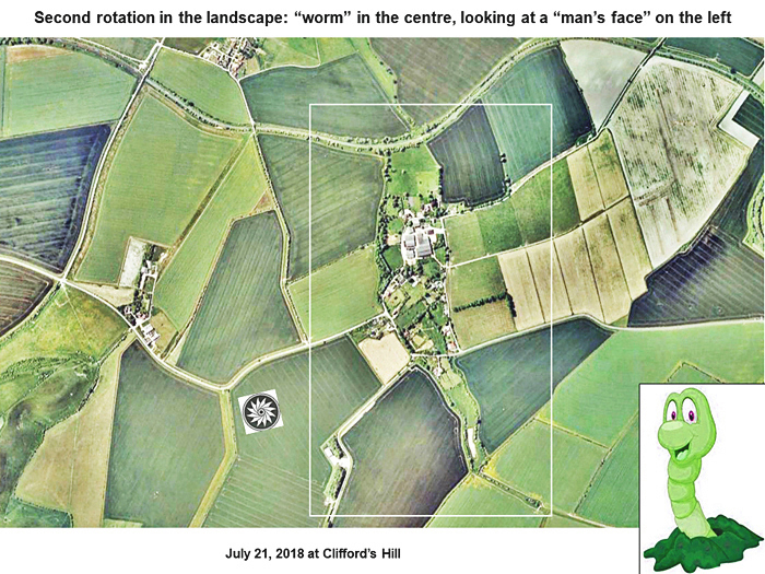
This “French
soldier” seems to be meeting a “happy serpent” face-to-face, as shown on
the right. The “happy serpent” is wearing the same kind of “feathered
military hat” as the “French soldier”. Any “serpent” image of this kind
which appears in crops, or which might be seen in the landscape nearby,
usually symbolizes the crop-artist Quetzalcoatl whose name means
“bird-serpent”.
What are we
to make of this strange “pinwheel” crop picture, and its two overlapping
symbolisms in the landscape, which they drew a “turning electric motor”
to help us locate? Personally I suspect that these are cryptic “images
of future” as drawn by time-travellers. Sometime in the next decade, our
crop-artist friend Quetzalcoatl may perhaps join French military forces
to help defeat a common enemy, whether from this world or another.
Likewise in
2016 we saw a field image of “sharks circling a Celtic triquetra” (see
ridgeway 2016 ),
in 2015 we saw written “timeo ET ferentes!” (see
Aeroporto commentsl ).
and in 2002 we saw written “Much pain but still time.” (see
time2007nl ).
Red Collie
(Dr, Horace R. Drew)
P.S. Other
related aspects of the Clifford’s Hill crop picture may be reported
later. Thanks especially to Nick Bull and Maya48. |