|
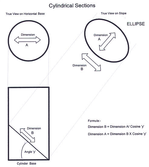
Many crop circles, in fact probably most, have occurred on hillsides or sloping ground. Also over the years there have been reports from witnesses and also other indications, that suggest that whatever the force is that creates them, it is projected down on to the earth from a perpendicular position directly above, almost as if from a 'Spotlight' suspended from a balloon. There have also been reports that many of the 'circles' , when carefully measured, are not true circles, they are ellipses. They turn out to have major and minor axes to a greater of lesser degree. Two fairly obvious conclusions can be drawn from the above information: 1. Circle hoaxers cannot produce ellipses with the equipment they use to create circles. A central anchor point and a rope tie will always produce a circle, whether on a hillside or on the flat. Any movement of the single central anchor point, either deliberately or accidentally will merely result in a deformed circle. This is not to say that an ellipse cannot be produced in a crop field. There is a well known method of drawing an ellipse which requires two foci and a connecting line, (any would be hoaxer wanting to try using it please contact me), but only the intention to deliberately, not accidentally, create an ellipse would call for its use. It follows from the above, that where circles, obviously intended to be circular, show ellipticality when measured they must generally be genuine, whether on a slope or on a flat. 2. If the theory proposed in the first paragraph above holds good then a genuine circle, found on a hillside , is capable of confirming that its forming force was projected perpendicularly downwards (or maybe an earth energy projected upwards?), because there is a mathematical relationship between the three components of:- 1. Angle of the incline. 2. The measurement of the down slope axis, and 3. The measurement of the horizontal axis across the hillside. If, a parallel beam of light designed to produce a circular image, is projected downwards on to a true horizontal surface, The beam of light, seen from the side will appear as a Cylinder standing on the base horizontal surface An illuminated true circular image will be seen on the base surface. If the base is then raised at one side so as to form an inclined surface for the light to fall upon the image will become an ellipse. The measurement across the image, ‘Dimension A’ in the Diagram "Cylindrical Sections" will be unchanged whatever the inclination of the base surface but the down slope measurement, ‘Dimension B’ in the diagram, will lengthen in proportion to the increasing inclination of the base surface. The Diagram "Cylindrical Sections" is an illustration of the geometrical principle that an Ellipse is a ‘Section of a Cylinder’ and that the dimension of the major axis of the ellipse is a function of the Cosine of the ‘angle of inclination’ from the horizontal. Given any two components of the three involved the missing component is very easily found. with any electronic calculator having trigonometrical functions. See the calculation examples given in the Diagram Cylindrical Sections'..
Jack Sullivan April 1999 |