|
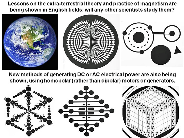
Part X. Extra-terrestrial physics as shown in crops: could there be another fifth dimension accessible from our three dimensions of space and one of time, which is spinning, hyperbolic, and has the symmetry of a Mobius strip? And could this be the “vector space” of quantum theory? Appendix 4. Spin, electricity and magnetism: the extra-terrestrials are teaching us about homopolar motors, and how they may be used to generate DC or AC electricity in a clean and efficient fashion “Before many generations pass, our machinery will be driven by a power obtainable at any point of the universe. It is a mere question of time before men will succeed in attaching their machinery to the very wheelwork of nature.”---Nicola Tesla, 1891 (see www.youtube.com) The scientific information shown in crops from 1994 to 2012 is truly extensive, although not always complete. It seems to focus on astronomy, mathematics, biochemistry and electromagnetism. An element of “time travel” seems impossible to avoid. Some crop pictures dealing with astronomy, for example, have predicted cometary events which lie months or even years into the future (see scorpius hour or time2007g or time2007h or time2011a). The new comet C/2012 S1 (Ison), which is expected to shine brightly in Earth’s skies during November of 2013 (see news.discovery.com), was drawn schematically in crops as long ago as 1996 (as will be reported soon on this website). Their mathematical images include a famous “pi to ten digits” drawing in 2008, which had never been thought of before on Earth (see www.dailymail.co.uk). Their biochemical images include detailed, accurate atomic drawings of melatonin or vitamin A (see roundway-hill-cropcircle-2011 or ogbourne-down-cropcircle-2012 or 4 mile clump). Sometimes they show “intellectual puzzles” which are not related to one specific branch of science or another (see time2012a or time2012b). Recently we have focused on understanding their drawings which describe electricity, magnetism, or the novel uses thereof (see Fringe2012a or fringe2012c or fringe2012g or www.cropcircleconnector.com/anasazi/fringe2012h.html). Also we have studied a whole series of images which tell about “extra spatial dimensions” (see fringe2013b). Three previous Appendices to our study of extra dimensions deal with: (1) quantum spin, the Born postulate and Bell inequality, (2) magnetism and spacetime wormholes, or (3) deBroglie waves, length contraction and extra dimensions (see fringe2013b or Appendix_3._deBroglie_waves,_length_contraction_and_extra_dimensions). The “Nobel Prize” crop pictures More recently, we reported how all three Nobel Prizes for Physics in 2009, 2010 or 2011 were drawn schematically but lucidly in crops, four months before they were awarded in Sweden (see near the top of crop circle research). Those prizes were for the CCD chip of digital cameras, graphene as a solar electricity cell, or quasi-crystals and their electron diffraction patterns. Once again, an unmistakeable “time travel” element enters our perception when studying crop pictures. Those extra-terrestrial races are apparently following our current scientific progress very closely, and are making crop pictures in English fields, four months in advance of the fact, to demonstrate that they have time-travel capabilities. What is the long-term purpose of “crop circles”? Are crop circles just an intelligence test, given openly to humans on Earth to see how we respond? Or do extra-terrestrial races hope to “seed” new technologies on Earth by means of crop circles, so that we will not kill ourselves through the excess use of oil, coal or gas? There has been a small but significant response to the artistic features of crop circles among ordinary people. Yet the response of Earth’s scientific community has been nil to irrationally negative. It is embarrassing to imagine how narrow-minded our “scientists” must appear, to advanced races from other worlds. For that reason, it is important to post a long and comprehensive explanation of recent crop circles in terms of “hard science”, even though most mainstream scientists will refuse to look. Such technical explanations will be available over the Internet to a collection of benevolent races, who drew such field images, and they will know that their efforts to communicate with us have not been in vain. I have been trying to enlist some competent physicists, skilled at magnetism, to build the new devices shown in crops. So far such efforts have not been successful. Most people on Earth today, including scientists, have been so brainwashed by continual lies and peer pressure, that they cannot recognize the truth when it is laid down right in front of them. Just like George Harrison and Sam Brown sang (see sam-brown-quot-horse-to-the-water-quote): “You can take a horse to the water, but you can’t make him drink, Oh no, oh no, oh no. You can have it all laid down in front of you, but it don’t make you think, Oh no, oh no, oh no.” Colonel Philip Corso, former chief of the Foreign Technology Division of the US military, confirms here that crop circles have been taken seriously for a long time in government workplaces (see www.youtube.com). Overall plan for Appendix 4 to Part X In this final Appendix 4 to Part X, we will discuss “electricity and magnetism” as shown in crops from 1994 to 2012. This new Appendix will be fairly long and comprehensive, so that a casual reader will not have to go back and read prior work:
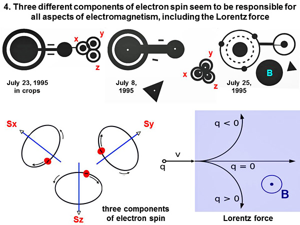
First we will recount some basic aspects of electricity and magnetism as shown in crops, using a simple conceptual model which will make it possible even for a non-scientist to understand their more complex field images. Their understanding of magnetism seems to be “extra-dimensional”, and derived from particle spin in higher spatial dimensions. Secondly we will discuss a series of “magnetic motor” images from the summer of 2012, which appeared in England, Brazil or the USA, often close to electrical power lines. Many of those field images showed “homopolar” motors or generators, not “dipolar” as used commonly on Earth. Thirdly we will give a brief review of how magnetic physics developed on Earth, beginning in 1820 with Oersted, and ending in 2012 with the “Mansuripur paradox”. Fourthly we will discuss the one-piece homopolar motor, and suggest several new experiments (based on crop-circle images) that may lead to a clarification or improvement of its action. Finally for inventors, we will summarize a series of different models for “magnetic motors or generators” which have been drawn in crops, and give brief notes on how to build them. Magnetism as an intersection of our 3-D space with subatomic spin motions in extra dimensions The most basic premise of “magnetism”, as shown in crop circles, is that it derives somehow from an intersection of our 3-D space with subatomic spin motions in extra dimensions. Here in three crop pictures from 1995 (see www.cropcirclecenter.com), we can see a schematic diagram for the “Lorentz force” of electromagnetism. That motif was accompanied in two cases by “three small balls”, which could plausibly represent the three components Sx, Sy and Sz of electron spin:
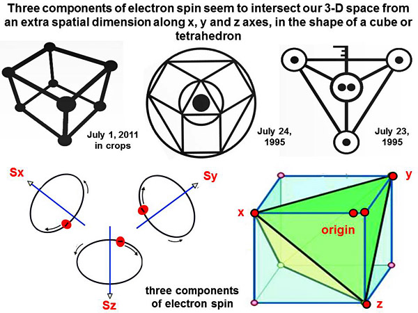
Those three components of electron spin are known to intersect our 3-D space equally along x, y and z axes in the shape of a cube or tetrahedron, at least for spin values of s = ˝ in units of h/2π. Three examples are shown of cubes or tetrahedra, two from the summer of 1995:
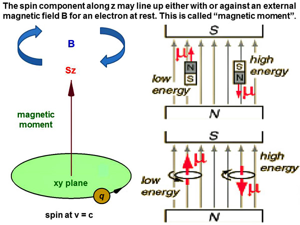
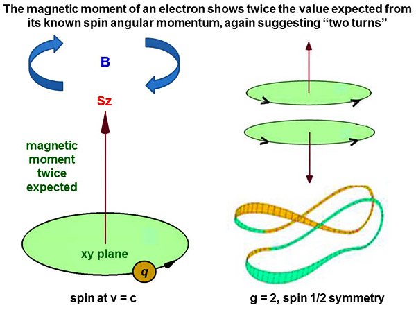
As standard background information, a spin component along the z axis as “Sz” may line up either with or against an external magnetic field B, for the electron at rest. This is called “magnetic moment”:
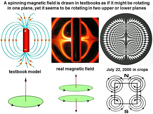
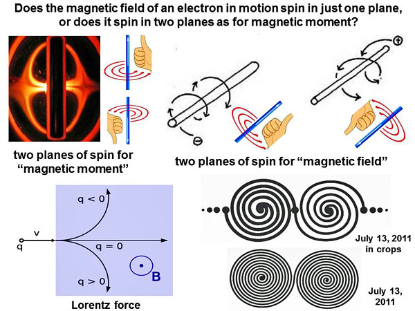
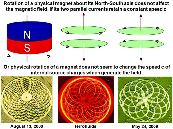
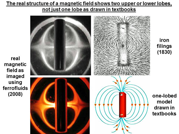
Does the magnetic field spin in one or two planes? We see in textbooks that a magnetic field supposedly spins in just one plane, as a simple “North-South dipole”. Yet when we study the same magnetic field using ferrofluids (see arxiv.org or nanomagnetics.us), or else in crops, it seems to be rotating in two upper or lower planes:
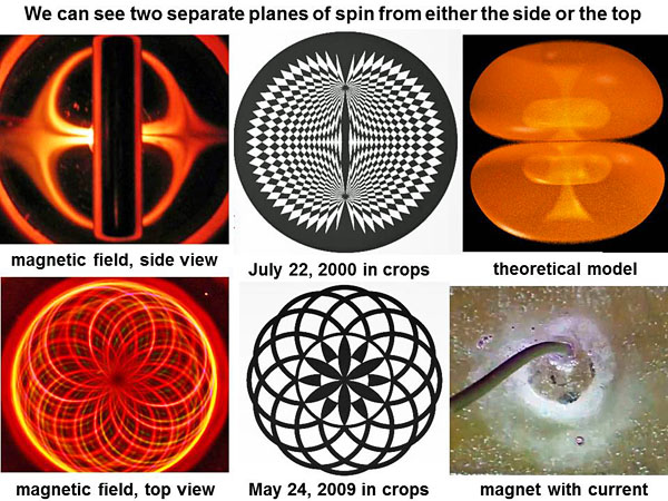
Using either ferrofluids or crop pictures, we can see two separate planes of spin, either from the side or from the top:
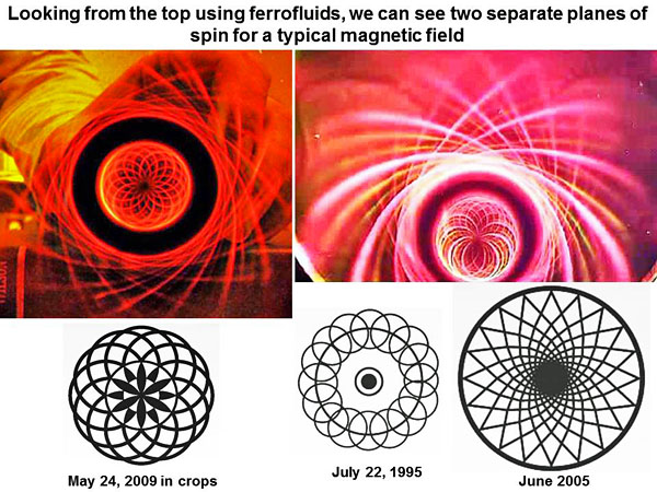
Images from the top, using ferrofluids, clearly suggest two planes of spin, and also match several crop pictures:
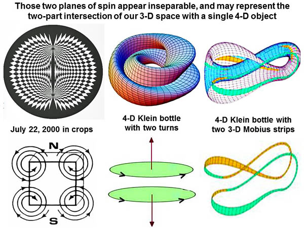
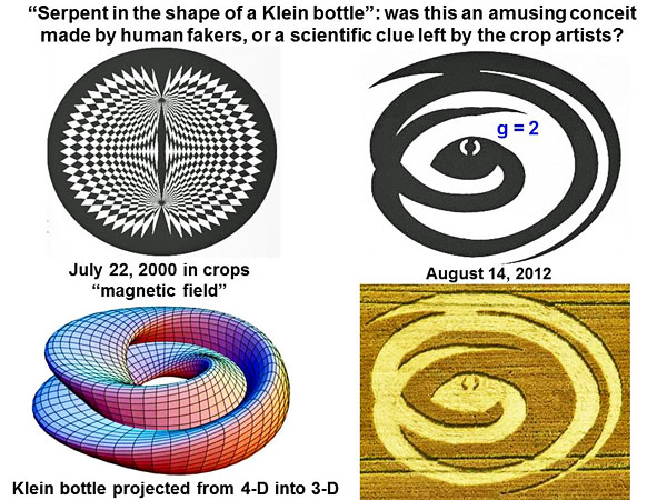
Why should a magnetic field show two planes of spin, rather than one? And why should those two planes be seemingly inseparable, since there are no magnetic monopoles just dipoles? One possible explanation is that the magnetic field actually exists as a “Klein bottle” type of shape in four or more spatial dimensions. When this unitary 4-D object intersects our 3-D space, then it appears to show two separate parts:
It has long been known that the magnetic field (at least on a quantum scale for an electron) has two very strange properties. First its magnetic moment is twice that expected for its known spin angular momentum, a characteristic known as “g = 2”. Secondly it has an odd topological symmetry of “spin ˝”, meaning that it rotates twice about one axis (say through space) for every single turn about another axis (say through time). These characteristics likewise suggest “two planes of spin”:
In August of 2012 we saw a humorous crop picture under the Uffington White Horse, which showed a “serpent in the shape of a Klein bottle”. Several advanced “magnetic” crop pictures were appearing at the same time in nearby fields (see below). Was this just an amusing conceit made by human fakers, or was it a scientific clue left by the real crop artists?
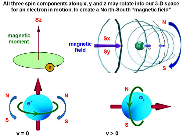
Magnetic field for an electron in motion When an electron begins to move with velocity v > 0, we can see a change in its properties from “magnetic moment” to “magnetic field”. Only one spin component Sz contributes to magnetic moment, while all three spin components Sx, Sy or Sz may contribute to a “magnetic field”:
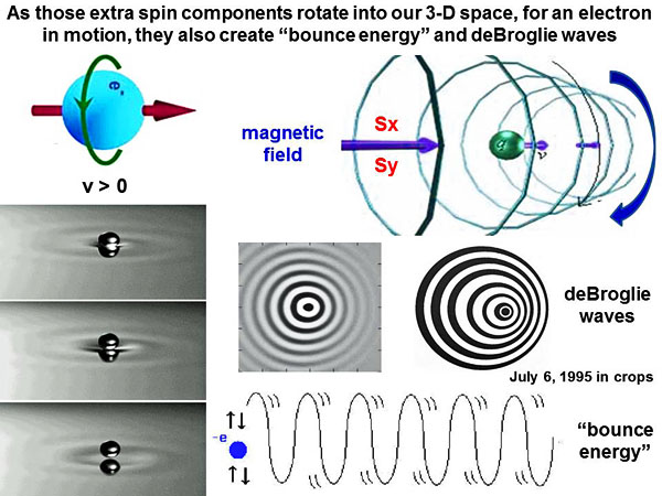
As those extra spin components rotate into our 3-D space, they also seem to create “bounce energy” and its associated deBroglie waves (see Appendix 3 of Part X on Appendix_3._deBroglie_waves,_length_contraction_and_extra_dimensions):
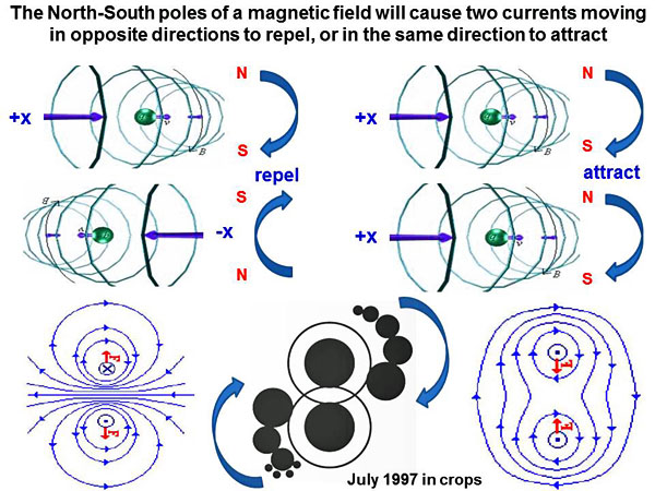
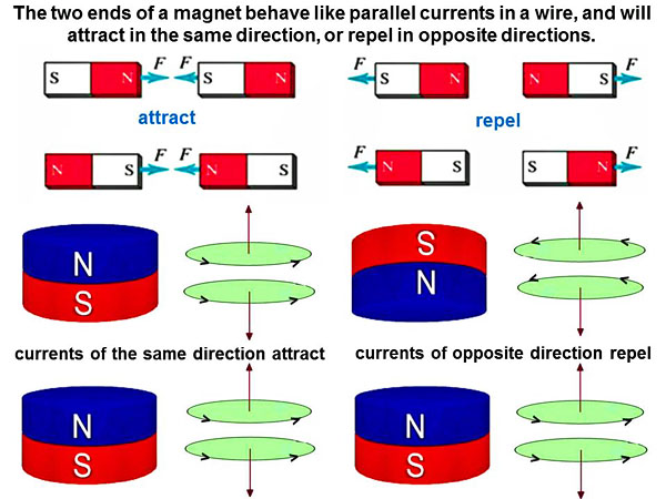
Again as standard background information, the North-South poles of a magnetic field will cause two currents moving in opposite directions to repel, or two currents moving in the same direction to attract (see a crop picture from 1997 at the bottom of that diagram):
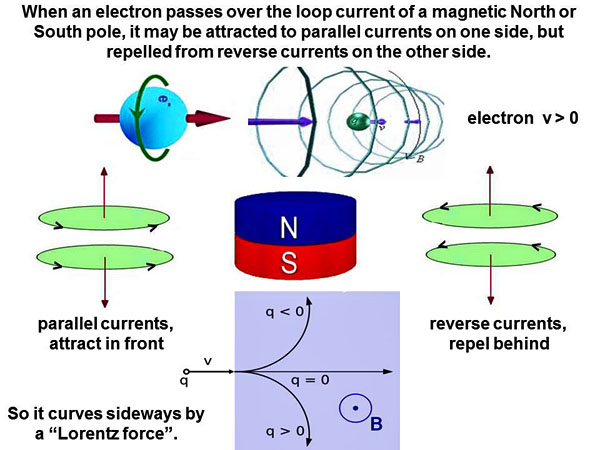
What happens when an electron (or electric current) passes over the North or South poles of a magnet? Now the electron (or electric current) experiences a sideways or tangential force (see www.youtube.com). Such a force could be explained in several different ways. One concise explanation would be that the moving electron is attracted to parallel currents within the magnet on one side (in front), but repelled from reverse currents within the magnet in the other side (behind):
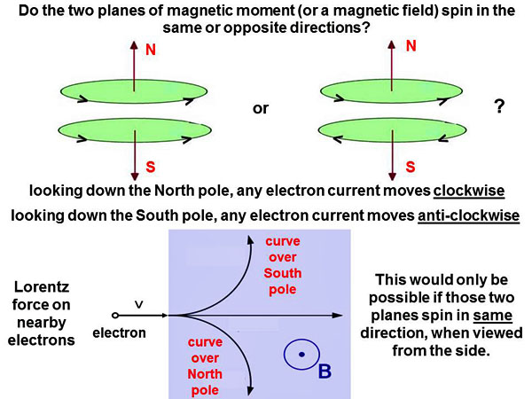
One plane of spin or two, and do they spin in the same or opposite directions? Once again we may ask: does a magnetic field spin in just one plane, or does it spin in two planes as for magnetic moment? Two “double spiral” crop pictures from 2011, shown at lower right below, appeared just after series of “magnetic” crop pictures in fields nearby:
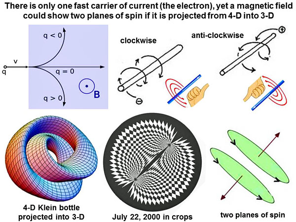
There is only one fast carrier of electric current in wires (the electron), but a magnetic field could show two planes of spin, if it is projected from 4-D into our 3-D space. A detailed image of the “magnetic field” as drawn in crops on July 22, 2000 also seems to show “two upper or lower planes”:
Supposing that the magnetic field really does show two planes, do those planes spin in the same or opposite directions? I have included this slide because the question is both subtle and confusing. Careful consideration shows that the two planes of any magnetic field must spin in the same direction, to produce outward effects on other charged particles as observed:
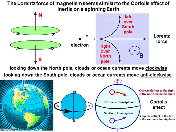
One can think of magnetism very qualitatively in terms of the “Coriolis effect”. It produces clockwise or anti-clockwise motions along the surface of a rotating Earth (see www.youtube.com):
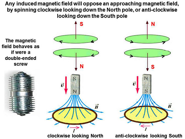
As standard background information, any induced magnetic field (with its two planes) will oppose an approaching magnetic field, by spinning clockwise while looking down the North pole, or anti-clockwise while looking down the South pole. The magnetic field behaves as if it were a “double-ended screw”, more than a simple “linear dipole”:
Strange properties of ordinary magnets We need to continue here with a little more background information, because otherwise when we present a series of complex “magnetic” crop pictures, the reader may have no idea what they mean, nor will he or she be able to follow the explanations given. When two magnets attract or repel one another, we can again imagine that two currents running the same direction attract, whereas two currents running in opposite directions repel:
Strangely enough, rotation of a physical magnet about its North-South poles does not affect the outward magnetic field. It is not known for certain why this is the case. One explanation might be that charged electrons, which are spinning inside of that magnet, already travel at light speed c, so they cannot go any faster when the magnet rotates. Another explanation might be that source charges (protons or electrons) inside of that magnet keep a constant velocity relative to one another, even though the magnet rotates:
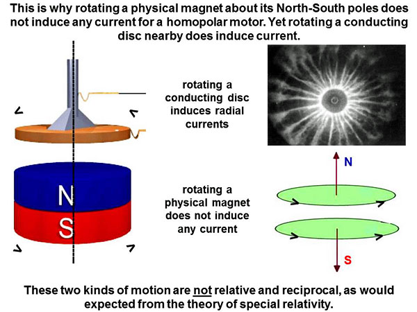
This is why rotating a magnet about its North-South poles, within a “homopolar motor”, does not induce any electrical current. Yet rotating a conducting disc above the magnet does induce an electrical current:
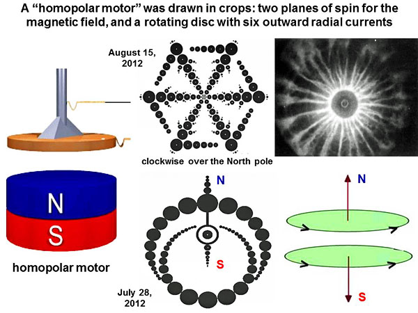
These two kinds of motion are not reciprocal and relative, as would be expected from Einstein’s theory of special relativity (1905). If it does not agree with accepted theory, then let’s leave it out of physics textbooks, so the students won’t become confused! The homopolar motor as drawn in crops (July-August of 2012) In the late summer of 2012, those extra-terrestrial crop artists drew a whole series of homopolar magnetic motors in crops, whether in England, Brazil or the USA. First we will show a few of their field images, then we will explain how “homopolar motors” are different from the “dipolar motors” (invented by Nicola Tesla) which power many of Earth’s industries. Their first image of a “homopolar motor” came down in two separate parts. A “North-South magnet” was drawn at Etchilhampton on July 28, 2012, while a “rotating and conducting disc” was drawn at Wappenbury on August 15, 2012:
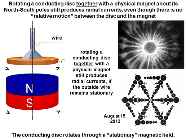
You can see that their “magnet” contains two separate spinning planes, just as described above. The number of circles in each plane give a mathematical ratio close to π/2 in radians or 90o, telling us to rotate those two broad arcs out of the field by 90o, in order to represent the magnet in three dimensions. Their “rotating and conducting disc” shows six outward radial currents, which curve clockwise by the Lorentz force over a “magnetic North pole”. For the homopolar motor, there is yet another strange anomaly, which again seems to contradict Einstein’s theory of special relativity. When you rotate both the North-South magnet and the conducting disc together, there is no “relative motion”, yet still we see a normal amount of electric current induced:
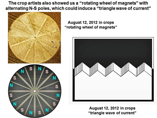
One could imagine that the conducting disc rotates through a “stationary” magnetic field, and thereby “cuts lines of flux” as Michael Faraday once suggested. Yet this behaviour is contrary to what would be predicted at face value from the theory of special relativity. Are the crop artists trying to draw our attention to certain paradoxes, and thereby tell us that parts of electromagnetic physics as taught today on Earth are wrong? Before going further, we again must pause to provide background information. What is the difference between a homopolar and dipolar magnetic motor (or generator)? A homopolar or unipolar motor (or generator) is created by the motion of some conducting material (or fluid) across one pole of a magnetic field, whether North or South. It works by (or generates) a steady stream of direct current (DC) (see www.youtube.com or homopola or RickerUnipolar1 ). A dipolar generator may be created by the motion of some non-conducting material or fluid (say water or wind), which is used to turn a conductive wire loop inside of the two poles of a magnet (North and South). It can also turn the two poles of a magnet (North and South) inside of a wire loop. This produces a discontinuous stream of alternating current (AC). Often a “commutator” is attached to a dipolar generator, in order to switch the direction of induced current flow from AC to DC. A dipolar generator can generate three-phase AC power, if the rotating N-S magnet is surrounded by three separate loops of wire spaced 120o apart (for example at Niagara Falls). Differences in the velocity of rotation for large astronomical objects such as our Sun, which turns slightly faster at the poles than the equator, may act as homopolar generators on a large scale, to produce huge electrical currents or powerful magnetic fields. Experimental properties of a homopolar generator We say that a homopolar generator consists of “two pieces”, if it is made from a magnet and a conducting disc, or of “one piece” if it consists of a magnet alone. When the conducting disc of a two-piece homopolar generator rotates, its conductive electrons move in a circle over the N-S magnetic field, so they experience a sideways or radial “Lorentz force”. This force (as described above) literally “pushes” those mobile electrons toward the outer rim of the rotating disc, or else toward its central axis if the sense of current is reversed. In the case of a two-piece homopolar generator, a conducting disk is placed above one pole of a cylindrical N-S magnet. If the disk rotates while the magnet does not rotate, there is an induced current. If the disk does not rotate while the magnet rotates, there is surprisingly no induced current. If the disk and magnet rotate together (while an outside wire remains stationary), there is again surprisingly an induced current. Two of these three cases apparently violate Einstein’s theory of special relativity. In the case of a one-piece homopolar generator, only a conducting magnet and external wire circuit are required. If the magnet rotates while an external wire circuit does not rotate, there is an induced current. If the magnet does not rotate while the external circuit rotates, there is an induced current. If the magnet and external circuit rotate together, there is no induced current (see www.k1man.com ). In this case, we see that “relative motion” between an outside wire circuit and the magnet is required to produce current, whereas in the former case, we saw that “relative motion” between a conducting disc and the magnet was not required to produce current. Michael Faraday, a great English inventor, was the first to study these phenomena in 1832: “When lines of force are spoken of as ‘crossing’ a conducting circuit, this must be considered as effected by translation of a magnet. No mere rotation of a magnet on its (N-S) axis produces any induction of current, in wire circuits exterior to it. The system of power about the magnet should not be considered as necessarily revolving with the magnet, any more than rays of light which emanate from the Sun must be supposed to revolve with the Sun. The magnet may even in certain cases be considered as revolving among its own forces, and producing an electric effect which is sensible at a galvanometer.” Can a homopolar generator produce alternating current (AC), if a ring of magnets alternate in polarity as N-S-N-S? At about the same time in 2012 when the crop artists were showing us a traditional “homopolar motor” (or generator), they also showed us a series of novel homopolar devices, which seem to work according to slightly different principles. Two new crop pictures appeared as a matched pair on August 12, 2012 at Stone Pit Hill or Devil’s Den. One of them showed a “rotating wheel of magnets” with alternating lays between each radial sector, suggestive of alternating N-S-N-S magnetic poles. The other showed a “triangle” or trapezoidal wave of induced current, which might be generated by that device as it rotates:
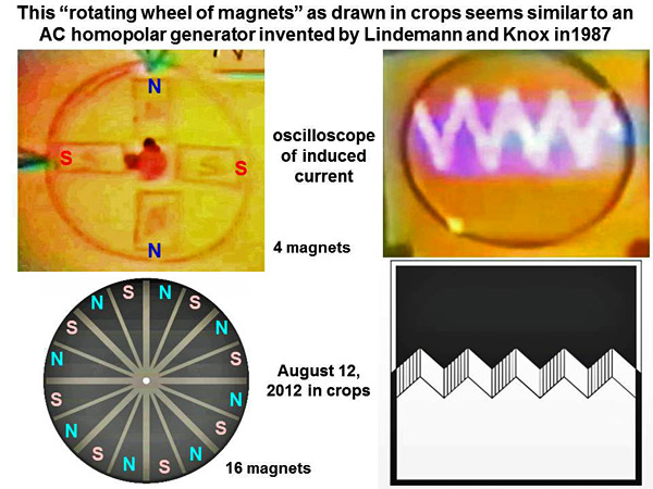
This “rotating wheel of magnets” as drawn in crops seems similar to an AC homopolar generator, which was invented (on Earth) by Peter Lindemann and Michael Knox in 1987 (see www.energeticforum.com):
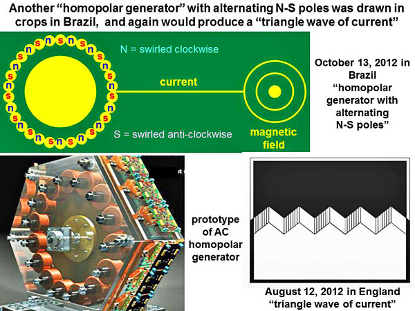
We can think of this device in terms of four one-piece homopolar generators (N-S magnets), arranged in a circle, and all rotating clockwise. If all four of those magnets were arranged as N-N-N-N or S-S-S-S, they would generate DC. Yet since four magnets are arranged as N-S-N-S, they generate AC. When rotating clockwise, each N-up pole takes current in radially, while each S-up pole passes current out radially. If you attach two brushes to nearby N-up and S-up magnets on the outside rim, both of their induced currents will go in the same direction. When any N-up magnet passes the first brush, the current will go one way. When any S-up magnet passes the first brush, the current will go the other way. Hence the overall power as generated by this device resembles a triangular wave of alternating electric current. Quite interestingly, you can also attach two brushes close to the axle of rotation (red dots), as well as along the outer rim (green arrows). Then a simple commutator-type of device may be used to collect electric power. The AC homopolar generator is practically unheard of on Earth, studied just by Lindemann and Knox in 1987, or more recently by Muller Power.in 2000-2010. All other generators of AC power on Earth are dipolar. Next in Brazil on October 13, 2012, we saw another kind of design for a homopolar generator to create AC power. In this case we saw 30 round magnets arranged around a large rotor, with alternating North-South poles as indicated by an alternating clockwise / anti-clockwise pattern of swirled crop. Nearby we could see a thin line leading toward the rotor, like a long current-carrying wire, and attached to that a double-concentric circle for “magnetic field” (see brazil 2012a):
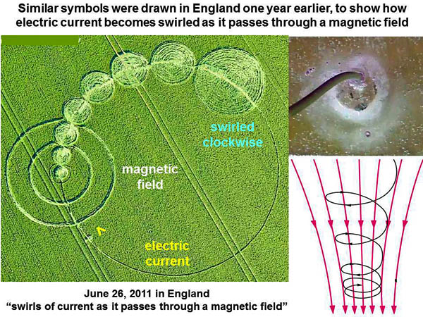
This Brazilian crop picture was drawn next to electrical power lines, the wires of which ran parallel to the “long line” shown in crops. It would again produce a triangle wave of AC power. A working prototype for an AC homopolar motor (from Muller Power in Canada) is also shown, which features alternating N-S-N-S magnets arranged radially on a wheel. It produces a triangular or trapezoidal wave of current (see mullerpower.com). One year earlier in England, we saw the same “double concentric circle” used to represent a “magnetic field” near Honey Street in Wiltshire. Electric current runs through that magnetic field along a long, round wire, in the direction indicated by a small “arrow” drawn in crops Then clockwise swirls of electric current come out the other end, still following the path of the wire as it curves around.
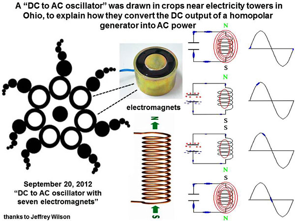
This image was one of six crop pictures drawn in a series near Honey Street in 2011, all dealing with “magnetism” or “magnetic motors”. Why are most crop pictures made in England? Why aren’t any made in the USA? Well, there have been some important crop pictures made in the USA, and investigated carefully there by a scientist Jeffrey Wilson, but the mainstream press have not reported such events widely. On September 20, 2012, an important crop picture appeared in corn near Hopewell Mounds in Ohio:
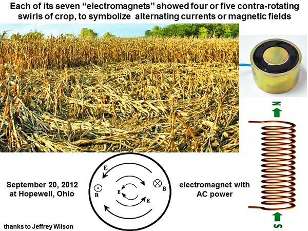
That crop picture was drawn close to electricity transmission towers, and seems to show a “DC to AC oscillator”, by which the DC output of a homopolar generator may be converted to AC for long-distance transmission (see hopewell2012b or hopewell2012a or www.electronics-tutorials.ws). It seems to show seven “electromagnets” around an oscillating centre. Why do we say they are “electromagnets”? Because each of those seven large circles contains four or five contra-rotating swirls of crop, exactly what alternating currents or magnetic fields would look like inside of an electromagnet:
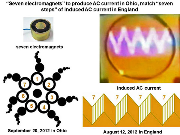
Elsewhere in the Ohio crop picture, we can see five small circles attached to each large “electromagnet”. Those were likewise laid down as clockwise, anti-clockwise then clockwise in series, for each small circle as a whole. Within its large central circle, all plants were flattened towards the centre radially. This may symbolize an “inward flow of current” from the outer parts. Two standing stalks of corn at the very centre may symbolize “two connecting wires”. Those “seven small steps” of AC power, shown at Devil’s Den in England in August 12, 2012, seem to match the seven steps of AC power which would be generated by “seven electromagnets” in Ohio on September 20, 2012:
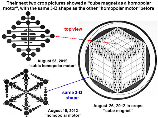
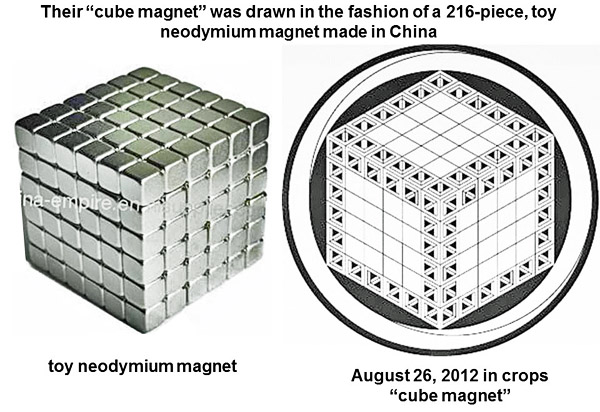
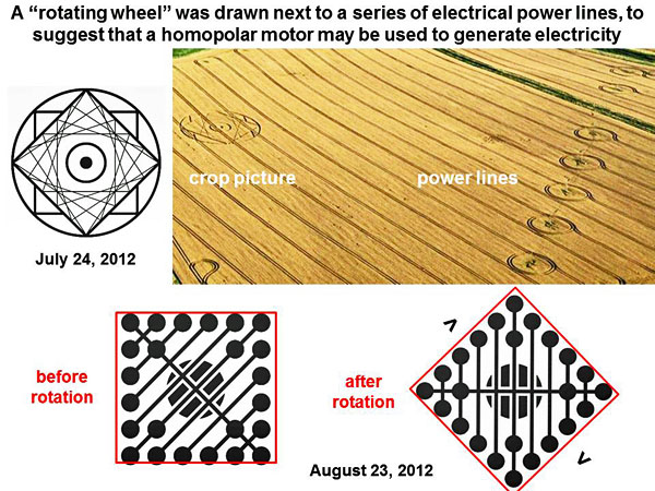
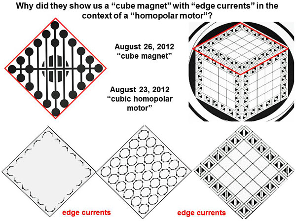
One might plausibly imagine that all of these crop pictures, whether in England, Brazil or Ohio, were made in August to October 2012 by the same collaborating group of crop artists. Their next two crop pictures in England during August of 2012: a homopolar motor made from a “toy cube magnet” Are we through yet? Is that all the crop artists showed us in 2012? No, we are still far from the end! We still need to consider their two most amazing efforts of the 2012 summer season: namely a “homopolar motor” which was drawn in two parts at Oxleaze Close on August 23, or at Hackpen Hill on August 26. It seems to be based conceptually (and somewhat humorously) on a “toy cube magnet” made in China. As shown in the diagram below, their two crop pictures on August 23 or August 26, 2012 both resemble in style the earlier “homopolar motor” from Wappenbury on August 15, whether by top view or by the same 3-D shape:
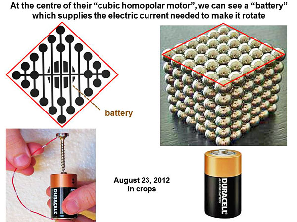
Their “cube magnet” of August 26, 2012 (viewed over half a million times on Crop Circle Connector, see hackpenhill2012c) was drawn In the fashion of a 216-piece, toy neodymium magnet from China:
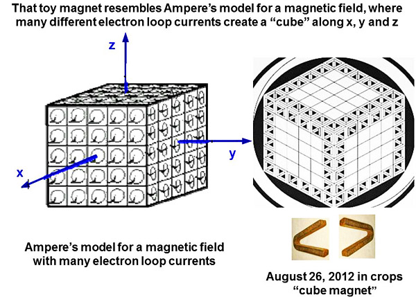
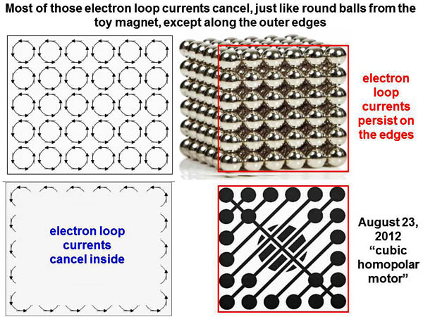
Why portray a homopolar magnet in terms of a “toy magnet”? Simply to teach us something about physics! The “toy magnet” resembles Ampere’s model for a magnetic field, where many different electron loop currents create a “cube” along x, y and z:
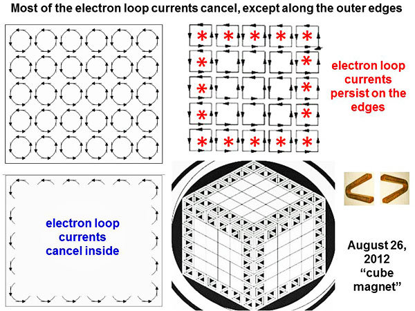
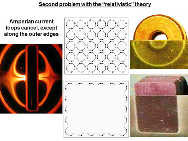
When we study loop currents more carefully, we find that almost all of them “cancel”, except along the outer edges of a magnet (see Chapter 8 of “New Magnetism” by Robert Distinti www.distinti.com or www.youtube.com).
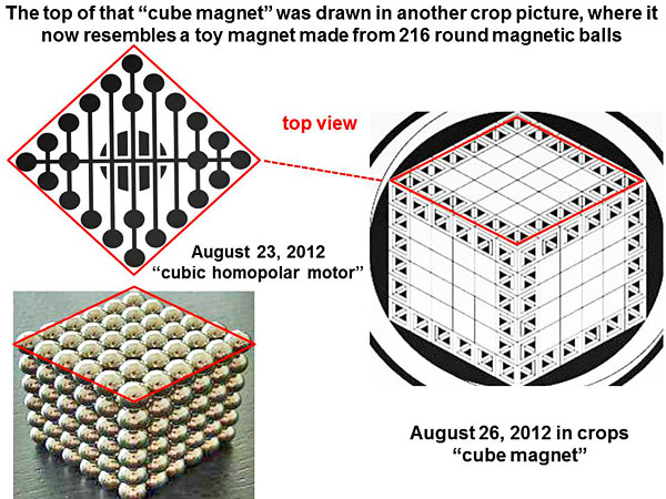
This is why the crop artist drew two little V-shaped magnets all along the outer edges of his “toy magnetic cube”, to symbolize local North or South magnetic poles, while he left all of the central squares blank. Next he drew a “top view” of that “cube magnet” in more detail at Oxleaze Close on August 23, 2012:
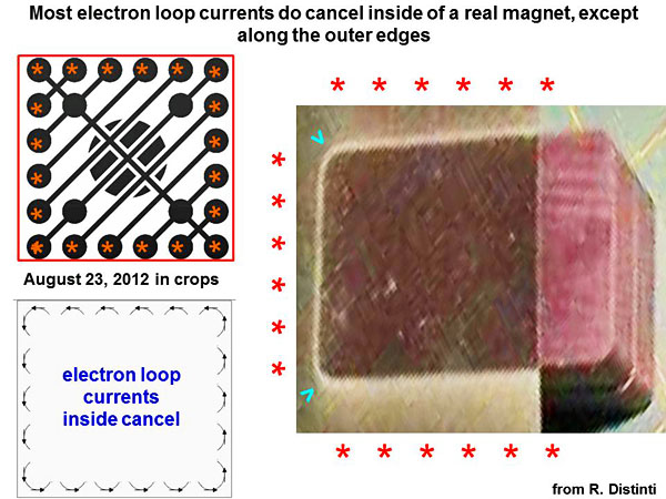
Now it resembles a toy magnet made from 216 small neodymium balls, rather than from 216 small cubes. Again most of the electron loop currents cancel, except along the outer edges (just as those small neodymium balls stick to one another inside, but leave exposed surfaces outside):
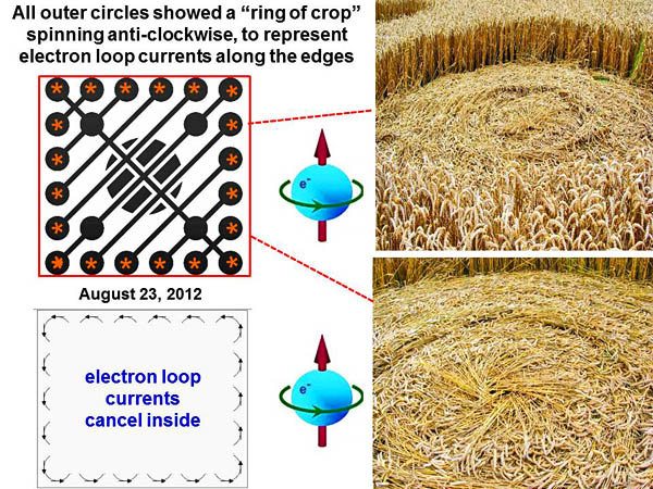
When we look at the Oxleaze crop picture in closer detail, we can see a small “ring of crop”, spinning anti-clockwise within all 20 of its outer-edge circles. Such rings have been labelled with “red asterisks” in the slide below:
Those small “rings of crop” seem to symbolize uncancelled loop currents, as just described above. If we look at real magnets, we can see those outer-edge loop currents very clearly, using a sheet of magnetic-sensitive film:
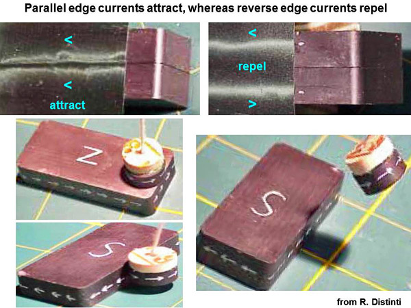
Parallel edge-currents attract, whereas reverse edge-currents repel, just like for ordinary electrical currents in a wire:
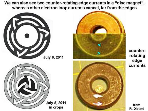
We can also see two counter-rotating edge currents in a disc magnet, as illustrated by two crop pictures from the summer of 2011, drawn just under the Milk Hill White Horse.
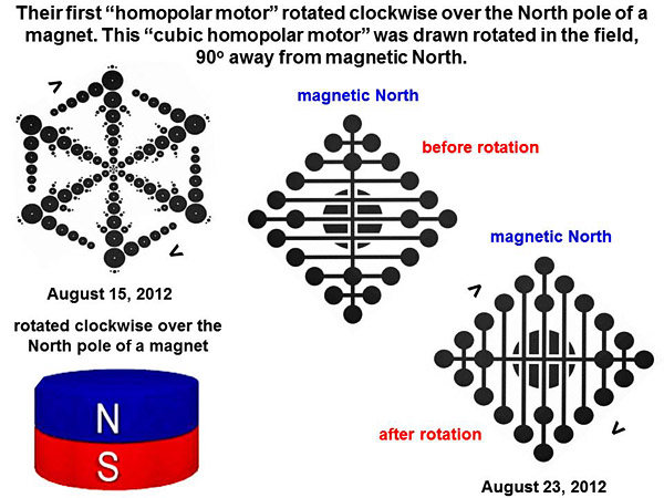
I arrived at the first phase of that crop picture on the morning of July 6, 2011, to find that its lines were marked out very sharply and precisely, as if they had been cut using lasers. There was no trace of prior human activity anywhere. Two days later on July 8, the second phase of that crop picture arrived during an intense wind and rainstorm, when no one could go out or fly. On the ground that crop picture lay several kilometres from the closest road, through wet muddy farmland. I drove up the side of Milk Hill with another researcher around noon on July 8, to get the first photos from on top of Milk Hill, although aerial photographers could not fly until the next day. Two homopolar motors, each rotating in the field Now what did their final two crop pictures in England, on August 23 or 26, 2012, mean in terms of electricity and magnetism? And how does that “toy cube magnet” with “outer edge currents” function as a homopolar motor? Their first “homopolar motor” as drawn at Wappenbury on August 15, 2012 was seemingly “rotating clockwise” over the North pole of a magnet. Then their next “cubic homopolar motor” as drawn at Oxleaze Close on August 23, 2012 was drawn rotated in the field, 90o away from magnetic north:
I checked the field orientation for both sets of crop pictures carefully. Etchilhampton of July 28, 2012 (their North-South “magnet”) pointed in the field approximately 10o to 20o west of geographical north, toward where Earth’s north magnetic pole is currently located as seen from southern England, close to 80o latitude North near Baffin Island in Canada (see Etchilhampton2). Oxleaze Close of August 23, 2012 was also aligned in the field 10o or 20o west of geographical north towards Earth’s north magnetic pole, along one of its four diamond-shaped corners (see Oxleaze Copse). Two other crop pictures from July of 2012 showed a similar “square of magnets”, with six on each side. These images confirm that the intended sense of rotation is clockwise:
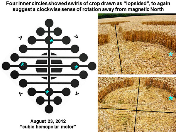
Four inner circles from Oxleaze Close on August 23 show swirls of crop which were drawn as “lopsided”, again to suggest a clockwise sense of rotation away from magnetic north:
We are indebted to Paul Jacobs for excellent ground photographs, which help to place the paranormal authenticity of this crop picture beyond any reasonable doubt. Other details of the “cubic homopolar motor” One of their July 2012 crop pictures, a rotating wheel with six “magnets” on each side, was drawn next to a series of electricity power lines. This may have been meant to suggest that a homopolar motor (or generator) may be used to generate useful amounts of electricity (see bishop cannings down).
Their “rotating wheel of magnets” was actually drawn
within a bowl-shaped depression at Bishop Cannings
Down, perhaps to suggest a bowl-shaped curvature of
space near strong magnetic fields (see “Wavefront
dislocations in the Aharonov-Bohm effect and its
water wave analogue, M.V. Berry et al,
European Journal of Physics 1, 154-162, 1980)
(Paul Jacobs, private communication). What makes the “cubic homopolar motor” rotate? At the centre of their field image from Oxleaze Close, we can see a large flattened circle which may represent a “battery” which powers toy homopolar motors, for thousands of amateur videos on YouTube.
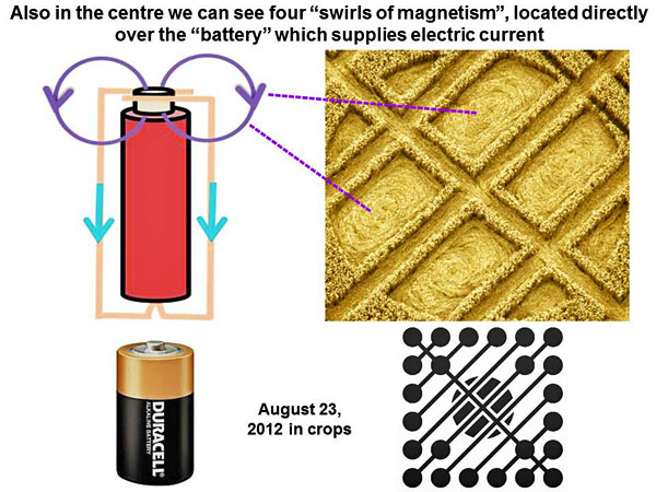
Also in the centre of Oxleaze Close, we can see four large “swirls of magnetism”, which lie directly over the “battery” that supplies electric current:
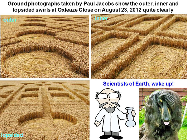
Ground photographs taken by Paul Jacobs show the outer, inner and lopsided swirls of crop at Oxleaze Close on August 23, 2012 quite clearly:
Scientists of Earth, wake up! Would you like to be known to future generations as akin to Italian academics of 1620, who refused to look through Galileo’s telescope at the moons of Jupiter, dark spots on the Sun, or phases of Venus? “Galileo expected his new telescope to quickly make believers in the Copernican system of all educated persons, but was disappointed. Soon he decided to address his arguments to the enlightened public, rather than hidebound academics” (see law2.umkc.edu). The academics of that time refused to believe in any evidence that Earth goes around the Sun, rather than vice-versa! Today they don’t even have to build a telescope to seek new knowledge, just go into the fields of Wiltshire. Yet still they refuse to look. It may be that some of these crop images were made by local fakers. Yet the vast majority, as judging from intellectual content as well as subtle field features, clearly were not. What was the scientific purpose of their last two crop pictures in August of 2012? All of these stylistic details are fascinating, but why did they show a “cube magnet” with “edge currents” in the context of a homopolar motor?
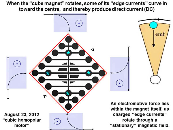
Their purpose seems to be one of informing us as to its exact mechanism. When the “cube magnet” rotates, some of its “edge currents” curve in toward the centre (blue asterisks in the slide below), and thereby produce a steady stream of direct current (DC):
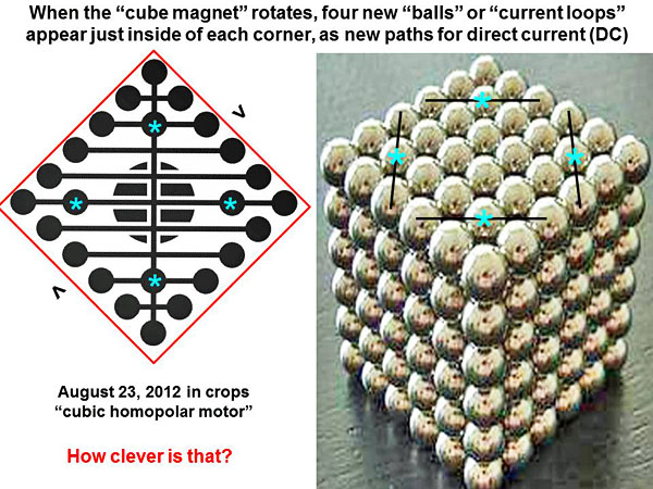
The electromotive force lies within the magnet itself, as charged “edge currents” rotate through a “stationary” magnetic field. When the “cube magnet” rotates, four new “balls” or “current loops” appear just inside of each corner, as new paths for direct current (DC). We can tell where those four “balls” are located, by reconstructing the crop picture in 3-D space:
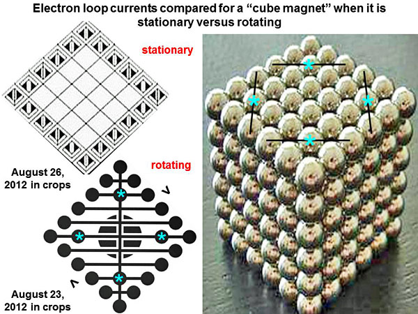
How clever is that? We compare, in the slide below, all locations of electron loop currents when the magnet is stationary versus when it is rotating:
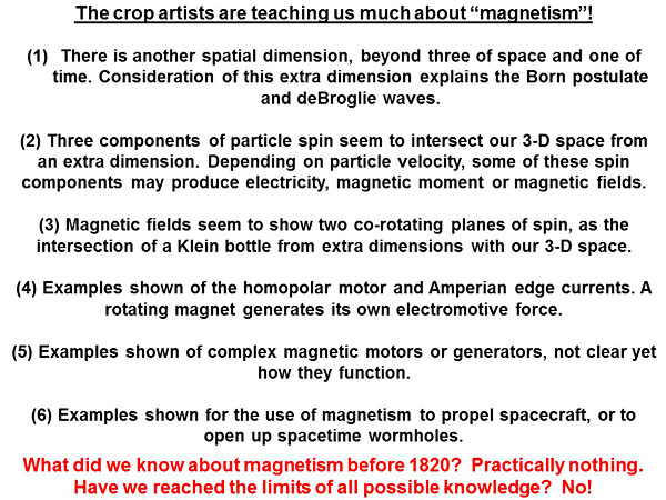
This is still a hotly-debated subject in electromagnetic physics on Earth. Various experts argue about whether the electromotive force of a one-piece homopolar generator lies in the rotating magnet, or rather in brush connections of that rotating magnet to an outside wire circuit. If the former is true, then our current interpretation of electromagnetic effects in terms of Einstein’s theory of special relativity seems unlikely to be correct. We will discuss these controversial issues more below. One other “magnetic motor” crop picture in this series, at Windmill Hill on October 14, 2012, remains unsolved (see windmill hill3). Summary and conclusions The extra-terrestrial crop artists have been teaching us quite a lot about “magnetism”. Some of the general conclusions from this long ten-part series are summarized in the slide below:
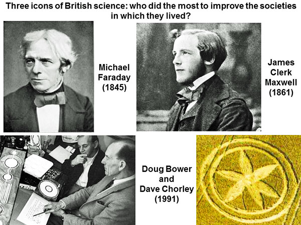
What did we know on Earth about magnetism before 1820? Practically nothing. Have we reached the limits of all possible knowledge? No! I will list at the end of this article a series of novel magnetic devices which have been drawn in crops, that open-minded inventors may wish to build. Only by further experiments can we progress, not by sterile mathematical arguments. Brief history of electricity and magnetism on Earth in recent times How did we get to where we are today? Not many people know about the modern history of research into magnetism, so I decided to include a brief synopsis (see also rroyalsocietypublishing.org). In 1820 a Danish scientist, Hans Christian Oersted, showed that if a compass needle is placed above or below a current-carrying wire, it will try to line up its long N-S axis as perpendicular to the wire. Two French scientists, Jean-Baptiste Biot and Felix Savart, then showed how the force on any magnetic pole N or S, due to current in a long wire, is proportional to the amount of current within the wire, and inversely proportional to perpendicular distance from the wire. Andre-Marie Ampere next showed how two parallel current-carrying wires would attract or repel, depending on whether their currents go in the same or opposite directions. In 1831, the English scientist Michael Faraday wound two separate coils of wire onto an iron ring. One coil was attached to a galvanometer to measure current, while the other coil was attached to a battery to produce current. When he switched on the battery to produce a current in the second coil, the galvanometer for the first coil (unconnected) flickered. It did so again when he switched the battery off. During the intervening time, current flowed in the second coil which was connected to a battery, but a galvanometer recorded no induced current in the first coil. Thus some changing magnetic field, as caused by an electrical current starting up or closing down, seemed induce other electrical currents in another coil nearby. Faraday also found that current could be induced by physically moving a magnet (again creating a changing magnetic field) through a wire coil which was attached to a galvanometer. No effect on the galvanometer was seen, if a magnet was held nearby but kept stationary. Current could likewise be induced by physically moving a wire coil, connected to a galvanometer, near a stationary magnet. Finally he discovered that the plane polarization of light could be rotated by a magnetic field, or by current flowing around a light beam. James Clerk Maxwell next wrote a famous series of theoretical papers concerning magnetism: “On Faraday’s lines of force” (1855), “On physical lines of force” (1861), “Dynamical theory of the electromagnetic field” (1864) and “Treatise on electricity and magnetism” (1873). By 1886, German physicist Heinrich Hertz had detected Maxwell’s “electromagnetic waves” as radio waves, and confirmed their velocity to be close to the speed of light c. Faraday and Maxwell were great icons of British science, who did much to improve the societies in which they lived. Can we say the same about Doug Bower and Dave Chorley, who claimed falsely to have made all of the crop circles in England prior to 1991? After which, that canard was spread by a deceptive press to the entire planet (a bit of humour here):
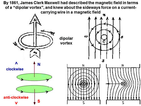
By 1861, James Clerk Maxwell had achieved a deep understanding of magnetism, and described the magnetic field in terms of a “dipolar vortex”:
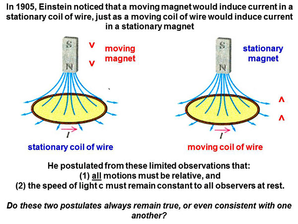
He also knew about the sideways force on a current-carrying wire in a magnetic field (which was later attributed to Lorentz). Poincare in 1904 and Einstein in 1905 suggested a novel “principle of relativity”. They argued that no experiment could distinguish one inertial frame from another. By assuming that Maxwell’s equations would follow this assumption, Einstein derived new relations concerning electrical or magnetic fields as seen in two different moving frames of reference. The electric field for one observer was hypothesized to be a combination of electric and magnetic fields as seen by the other observer, and similarly for a magnetic field. His basic postulates were derived from the case of a “moving magnet” and “moving conductor”, where all motions appear to be “relative”:
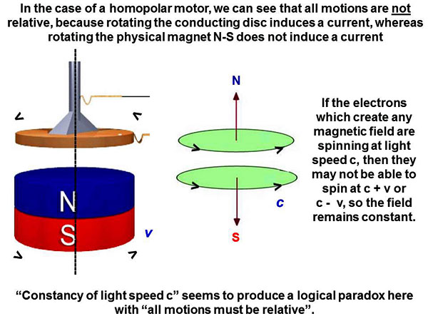
Had he included observations from the homopolar motor (or generator), for which motions between the magnet and conductor are not relative, then his theory in its present form would never have been accepted. There might be some other “theory of relativity”, but not this specific version with its two postulates of: (1) all motions must be relative, and (2) the speed of light c remains constant to all observers at rest, in their own frame of reference. One is entitled to ask: do these two postulates always remain true, or even consistent with one another? In the case of a homopolar motor, we can see that all motions are not relative, because rotating the conducting disc induces a current, whereas rotating the magnet does not induce a current:
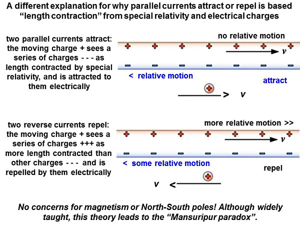
Likewise if the magnet and conductor rotate together, there is an induced current without any “relative motion” within the motor itself. It seems hard to know how to interpret those anomalies. Yet if the electrons which create any magnetic field are already spinning at speed c, then they may not be able to spin at speed c + v or c – v, so the magnetic field remains constant. “Constancy of light speed c” seems to produce a logical paradox here with “all motions must be relative”. According to modern physics as taught in the schools, all kinds of electromagnetic phenomena may be explained in terms of Einstein’s theory. This is called “relativistic electromagnetism” (see Relativistic_electromagnetism). For example, we can explain by the theory of special relativity why two parallel wires either attract or repel, depending on whether the currents which flow through them go in the same or reverse directions. A typical textbook explanation is shown below:
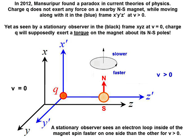
If we make clever postulates about “length contraction” or “altered charge densities”, we can use Einstein’s theory in this case to explain why two current-carrying wires either attract or repel. Without any concern for magnetism or North-South magnetic poles! This theory is widely taught, yet it makes incorrect predictions in more complex cases, for example in the “Mansuripur paradox” of 2012. The “Mansuripur paradox” of 2012 Mansuripur in 2012 pointed out that the theory of special relativity and Lorentz theory of electromagnetism do not seem fully consistent with one another. They can make different predictions for differently moving frames of reference. For example, a charged particle q and a N-S magnet may lie close to one another in space, while at rest or v = 0. The magnet contains many microscopic electron current loops, which spin perpendicularly to its North-South poles. Neither of those objects, the charged particle q or the N-S magnet, exerts any force at rest which might cause those two objects to move apart, move together, or twist in space. Now suppose we were to load both the charged particle q and the N-S magnet onto a flatbed truck, and drive that truck out onto an interstate highway at velocity v. Would some stationary observer, watching from the side of the road, see the same situation differently? It seems obvious that a stationary observer would see electrons on one side of the current loop move away from him faster, than electrons on the other side of the current loop:
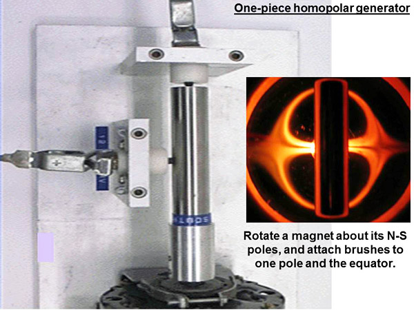
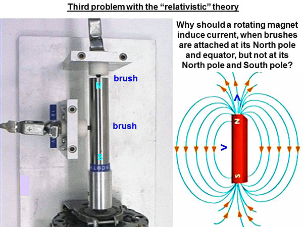
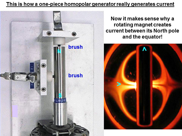
According to the theory of special relativity, any velocity v relative to an observer produces “length contraction”. By that theory, the stationary observer will see fast-moving electrons on one side of the loop as more length contracted, than slow-moving electrons on the other side. Since electrons are negatively charged particles, such a difference of length would pack them together more tightly on the “fast” side of the loop than on the “slow” side. If the nearby electrical charge q is positive, it will then be attracted more strongly to the “fast” side than to the “slow” side, thereby producing a torque about the magnet’s N-S poles. If the nearby electrical charge q is negative, it will repel more strongly the “fast” side than the “slow” side, producing a torque of opposite sense about the magnet’s N-S poles. None of this happens in real life! How have other physicists responded to this apparent absurdity, which is produced from their textbook theories? They have invoked a second imaginary effect called “hidden angular momentum”. The second effect supposedly accounts for the first effect, although neither can be observed (see news.sciencemag.org or www.physics.smu.edu). Did the crop artists show us “homopolar motors” in the summer of 2012, because they wished to inform us of an error in electromagnetic physics as currently taught on Earth? Or do they wish to teach us how to build new devices, based on a deeper understanding of magnetism? Let us conclude this article by studying the experimental properties of a homopolar generator, so we can decide whether “special relativity” really explains its mechanism or not. Two part-structure of a magnetic field, and a new explanation for the one-piece homopolar generator To conclude this article, let us study the action of a one-piece homopolar generator, which is essentially just a “rotating magnet”. In the laboratory we choose to rotate a cylindrical magnet quickly about its N-S poles. Two “brushes” have been attached to one pole (either North or South) and the magnetic equator. We find that rotating this magnet generates a direct current (DC):
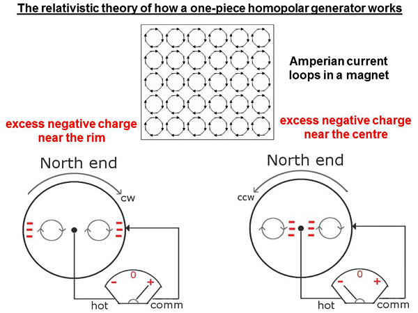
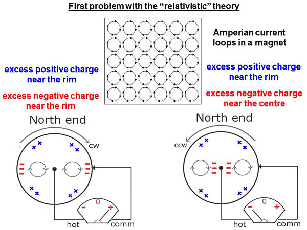
The effect remains inexplicable by classical theories of electromagnetism as taught in textbooks on Earth. No lines of magnetic flux are apparently “being cut”, nor are any electrical charges apparently moving through a magnetic field. Berg and Alley tried in 2005 to explain this effect by the theory of “relativistic electromagnetism” (see www.physics.umd.edu). Here is what they said:
A cylindrical magnet contains many electron current loops, as were discussed above in relation to 2012 crop pictures. When we look down the North pole of our rotating magnet, we will see that its “Amperian current loops” rotate either clockwise (on the left above) or anti-clockwise (on the right). When the magnet is rotating clockwise, “current electrons” near the top of any loop (near the outer edge of the magnet) will move faster than other “current electrons” near its centre. We may therefore see greater “length contraction” of current electrons along outer edges of the magnet (red dashes on the left above) than close to its centre. This will in turn produce a more negative charge-density along the outer edges of the magnet than near its centre. Thus a radial current of electricity will flow from the outer edges to the centre. If the magnet is rotating anti-clockwise, then current electrons will be more length-contracted near the centre of the magnet than along its outer edges (red dashes on the right above), and current will flow from the centre to the outer edges. There are three serious problems with this hypothesis. First, the authors do not seem to consider that protons within the magnet will also rotate clockwise (or anticlockwise), and hence will appear more length-contracted on the outer edges than near the centre, for either clockwise or anti-clockwise rotation:
Please see blue “plus” signs on the left or right above Those excess positive charges could cancel excess negative charges along the outer edge, or could reinforce excess negative changes near the centre. Hence the two cases of clockwise versus anti-clockwise rotation would no longer be symmetric in action as observed. Secondly, we know that Amperian current loops within real magnets cancel except along the outer edges. Thus when looking down the North pole of a cylindrical magnet, we will see uncancelled current loops mainly along the outer rim:
The “relativistic” hypothesis, as described above, requires that those current loops should span a wide range of radial distances from centre to edge. In that way, they may experience widely different “length contractions” as produced by widely different radial velocities. Many direct images of magnets by sensitive films or ferrofluids suggest this is not a major process. Thirdly, the two brushes which collect current from that rotating magnet have been attached to just one of the poles and the magnetic equator:
It certainly does not seem obvious, why induced current should flow from pole to equator for a rotating magnet, based on textbook models which show a simple dipole, in which there is no field structure near the magnetic equator? One might expect naively to collect current from two brushes attached to the North and South poles, if the simple dipole model shown above were correct! Instead the electromotive force from a rotating magnet turns out to be equal in strength, and opposite in direction, at a North pole versus a South pole. Two brushes attached to each polar end, measure no induced current at all. What we have shown above is a “textbook model” for the magnetic field, not something actually seen in high-resolution experiments. When we look at real images of a cylindrical magnet at high resolution (using ferrofluids), we can see that a physical magnet seems to be composed of two upper or lower lobes (see nanomagnetics.us), rather than just one lobe as drawn in textbooks:
This is also, of course, what the crop pictures show. Now it makes sense why a rotating magnet generates induced current between its North pole and the magnetic equator, because there is big, flat region of uncancelled edge currents just above (or below) the equator, as marked by a light-blue horizontal arrow in the slide below:
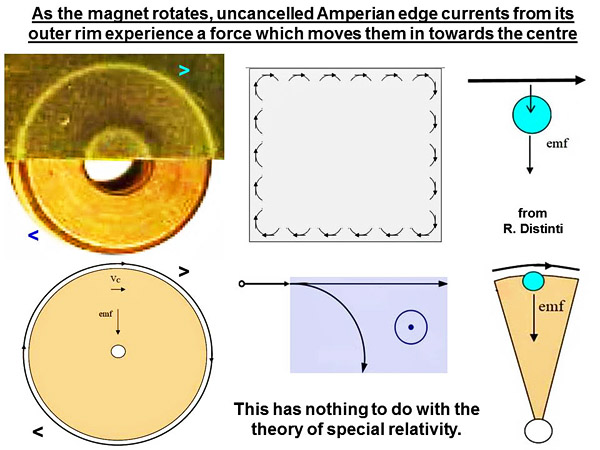
That large flat region may act like the conducting disc of a two-piece homopolar generator, and produce inward or outward radial currents between pole and equator, as it rotates through a “stationary” magnetic field. Perhaps Michael Faraday anticipated this result in 1832 when he wrote: “A magnet may in certain cases be considered as revolving among its own forces, and producing an electric effect which is sensible at a galvanometer.” In summary, as a magnet rotates, the uncancelled “edge currents” from its outer rim seem to experience an electromotive force which moves them in toward the centre (or toward the outer edges if its sense of rotation is reversed):
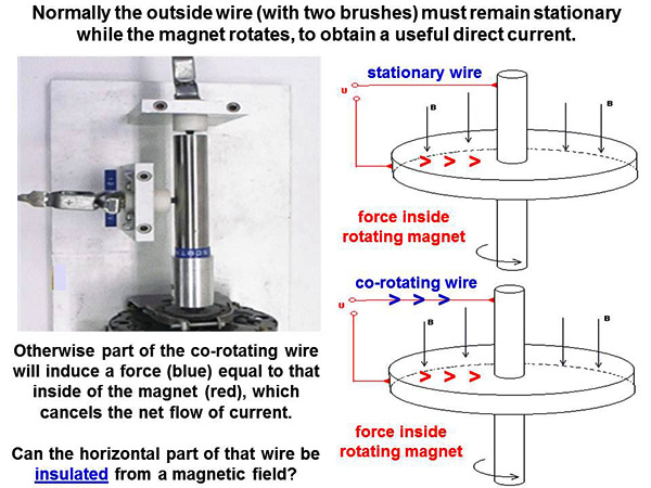
This has nothing to do with the theory of special relativity. Two suggestions for further experiments with a one-piece homopolar generator Normally the outside wire circuit which collects induced current from a homopolar generator must remain stationary, while the magnet rotates. Yet we might be able to circumvent this requirement, if a horizontal part of the outside circuit were to be “insulated” from its nearby magnetic field. Then it would no longer create an opposing electromotive force for a co-rotating wire (blue arrows in the slide below):
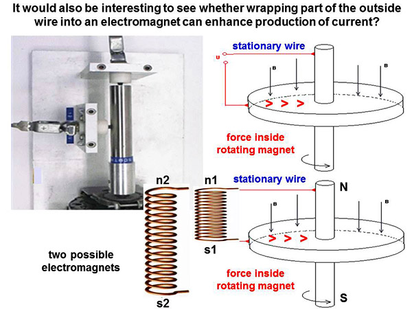
It would certainly be an experimental challenge to eliminate the second (blue) electromotive force, but this might be accomplished using “mu metal” (see /Mu-metal or www.lessemf.com) or a high-temperature superconductor (see Super conductivity). Likewise it would be interesting to see whether wrapping part of the outside wire into an electromagnet enhances the production of current, by strengthening the local magnetic field?
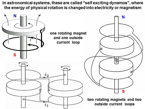
In astronomical systems, these are called “self-exciting dynamos”, where the energy of physical rotation from some conductive material or fluid is changed into electricity or magnetism (see dynamo_effect or www.phys.ens.fr/~dormy/Publications/Dormy06.pdf or www.iki.rssi.ru):
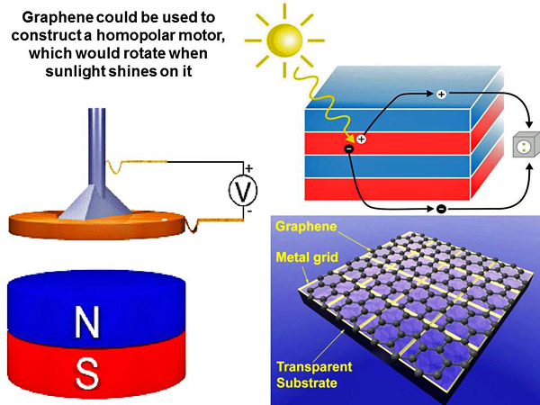
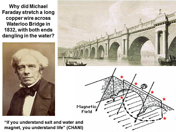
Large astronomical bodies such as the Sun, Jupiter or Earth generate strong magnetic fields by self-exciting dynamos, simply because lots of conductive fluids are moving around at different speeds, inside of the rotating object. Michael Faraday understood these physical principles long before anyone else. In 1832, he tried to harvest electricity from the motion of conductive saltwater in the Thames River under Waterloo Bridge (see www.phy6.org/earthmag/dynamos.htm). Almost all natural magnetic fields are generated by homopolar processes, not dipolar. Summary of novel magnetic motors or generators which could be built by inventors here on Earth Having understood all of these “magnetic” crop pictures, which were kindly shown to us by extra-terrestrial races, how can we move forward? The best approach would be for open-minded inventors to try and assemble some of the novel “magnetic motors” that have been drawn in crops, to look for novel or unexpected properties. We will list a few promising candidates here. First we have two dozen “magnetic motors” from the years 1991 to 2012 as listed in Table 1 of Part VI (see fringe2012c). It would be interesting to see how some of these might function? Then we have a cyclic homopolar motor which was drawn near Honey Street in 2011, where five N-S/N-S magnets were connected in series along the five sides of a pentagonal wire loop. What happens when electrical current runs through all of them, and produces a circular “ring of torque”? (see fringe2012a or time2012w or time2012t). Next we have a series of “homopolar motors” which were drawn in crops during the summer of 2012. The first was a standard conducting disc which rotates over a N-S magnet. The second (in England or Brazil) was a series of N-S-N-S magnets arranged in a circle. The third was a “cube magnet” rotating over an electrical battery. The fourth was a DC-to-AC oscillator using seven electromagnets. Please see some of the slides above for more information. Also we have two novel variants of the one-piece homopolar motor, which could be assembled and tested using: (a) an insulated wire loop for the outside path, or (b) an electromagnet for the outside path. Finally we have at least three models for magnetic propulsion drives, which have been garnered from studies of real UFOs, or from images of UFOs as drawn in crops. These would be the “reversible electromagnetic” drive described to policeman Herbert Schirmer in 1967 (see fringe2012g), the magnetic propulsion drives which were drawn in crops for several “UFO” images in 1998 (see fringe2012h), or “ring magnetic motors” which may be seen in “drone UFO” photographs from 2005 (see fringe2012a). Graphene as the conducting disc of a homopolar motor In late June of 2010, the crop artists showed us “graphene as a solar cell” at White Sheet Hill. Four months later, that discovery was awarded the Nobel Prize for Physics. It seems obvious that graphene could be used as the conducting disc of a homopolar motor, which would then generate electric current and rotate, when sunlight shines on it:
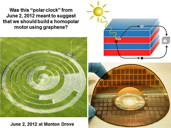
Was this “polar clock” crop picture from Manton Drove on June 2, 2012 meant to suggest that we should build homopolar motors out of graphene?
Thin sheets of graphene are currently being made on DVD discs, as shown above at lower right. The motor would turn of its own accord when sunlight shines on it, or else it could be made to turn in the dark, by supplying outside electrical current from a nearby power pole (as shown in the crop picture). Afghan hound or border collie? Do Earth’s scientists plan to remain “thick as a brick”, or do they wish to become really clever? One would have to be stupid as an Afghan hound, not to realize there is some valuable information here to be mined. How about it, magnetic physicists and inventors? Will you choose to be “clever as a border collie”, or alternatively as Jethro Tull sang, “thick as a brick”? (see www.youtube.com) There seem to be no prospects for any further advances in physics from particle accelerators in the near future, even if they cost $20 billion (see cosmiclog.nbcnews.com). For a fraction of that cost, say $20 million, any good magnetics lab could build prototypes of all the novel devices cited above. What are we waiting for? We know that many new “magnetic” technologies are available, so we should start to develop them now, before oil or gas-based pollution on Earth becomes any worse. Red Collie (Dr. Horace R. Drew, Caltech 1976-81, MRC LMB Cambridge 1982-86, CSIRO Australia 1987-2010) P.S. We would like to thank many of the researchers and photographers who have studied crop circles over the past 25 years. They have provided well-documented records for future generations, of our first modern contact with other advanced races not from Earth. They do not as a whole seem to have more academic intelligence than professional scientists, but they are able to trust what they see with their own eyes, and not just what other people tell them. This a different and perhaps more valuable form of intelligence than book learning. “During the eighteenth century, the French Academy of Sciences stubbornly denied the evidence for meteorites, which seemed massively obvious to everyone else. Scientists in other countries were anxious not to be considered as backward, compared with their famous colleagues in Paris. So many public museums threw away whatever they possessed of those precious meteorites. It happened in Germany, Denmark, Switzerland, Italy and Austria. Lavoisier (a leading French scientist) found iron pyrites in meteorites, and concluded that lightning had struck the rock, which peasants later misidentified as ‘falling from the sky’. On the subject of meteorites, he added that ‘true physicists’ had always been skeptical” (see arthur.shumwaysmith.com). In the context of this article, we would especially like to thank Paul Jacobs for his excellent ground-based images and technical advice.
|